1 convert to 3 wire circuit which will essentially eliminate the ambient temperature effects 2 convert to a 4 wire circuit in this case connection lead resistance effects completely eliminated.
Rtd temp probe wiring.
A resistance temperature detector rtd is a temperature measurement device that accurately uses resistance to measure temperature.
The connection lead are subjected to a large temperature change.
Rtd sensor in 2 wire circuit.
The connection lead are subjected to a large temperature change.
Rtd circuits work by sending a known amount of current through an rtd sensor and then measuring the voltage drop across that resistor at the given temperature.
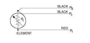
Because every pt100 element in the circuit containing the sensing element including the lead wires connectors and the measuring instrument itself will introduce additional resistance into the circuit it s important to be able to.
The resistance increases as the temperature of the sensor increases.
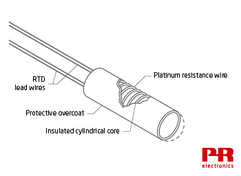
He wound a helical coil of platinum on a crossed mica web and mounted the assembly inside a glass tube.
1 convert to 3 wire circuit which will essentially eliminate the ambient temperature effects 2 convert to a 4 wire circuit in this case connection lead resistance effects completely eliminated.
2 wire 3 wire and 4 wire rtd explained.
The classical resistance temperature detector rtd construction using platinum was proposed by c h.
Difference between 2 wire rtd 3 wire rtd and 4 wire rtd s rtds resistance temperature detectors are offered with 2 3 or 4 lead configuration.
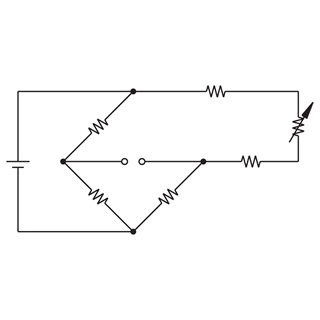
Below is a better configuration four wire kelvin connection.
It provides full cancellation of spurious effects.
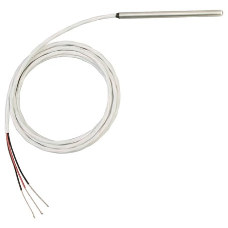
As rtd elements are fragile they are often housed in protective probes.
An rtd is a passive device.
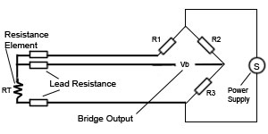
The above wheatstone bridge method uses a little more copper wire and is not a perfect solution.
The rtd wire is a pure material typically platinum nickel or copper.
It does not produce an output on its.
An rtd resistance temperature detector is a sensor whose resistance changes as its temperature changes.
Rtd sensor in 2 wire circuit.
The material has an accurate resistance temperature relationship which is used to provide an indication of temperature.
The best configuration for a specific application depends on a number of factors however the sensor configuration must match with transmitter otherwise leadwire resistance cancellation circuitry.
This construction minimized strain on the wire while maximizing resistance.
The 5437 2 wire hart temperature transmitter the 5337 2 wire transmitter with hart protocol and the 6337 2 wire hart transmitter can be programmed with these coefficients precisely matching the transmitter to a characterized rtd for exceptional measurement accuracy.
The resistance vs temperature relationship is well known and is repeatable over time.